NDT Condition Assessment Services
It is natural that plant machinery and equipment suffer from aging effects because of high temperature creep, fatigue, sgress corrosion, erosion and simple wear either acting or in combination contribute to the gradual degradation of the affected component integrity. The severe operational transients like temperature shoot up, over speeding and over loading etc., may contribute to acceleration of the degradation process.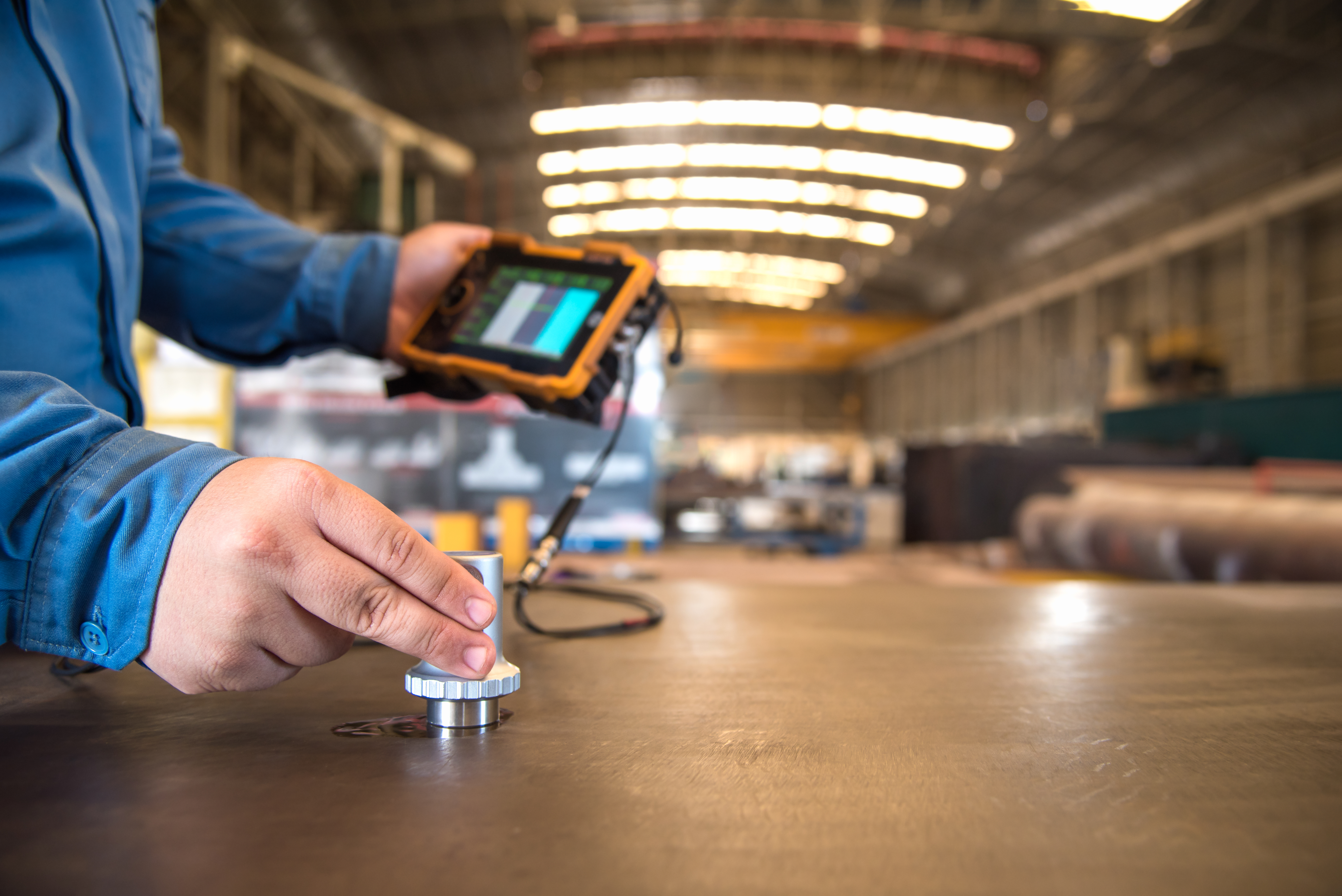
The purpose of NDT-based condition assessment study therefore is to evaluate the present condition of the components in terms of integrity and healthniness and to estimate future inspections, repairs, modifications / replacement based on projected usage, so that the economical operation of the unit can be optimized.
 We have several successful case studies weherein we could help customers correct the equipment imperfections, deteriorations through our integraged reliability maintenance services. ACMEI carries CONDITION ASSESSMENT studies on various components / equipments in sectors like POWER, PAPER, STEEL, CEMENT, CHEMICAL, ENGINEERING ETC.
BRIEF DESCRIPTION OF CONDITION ASSESSMENT ACTIVITES
1) VISUAL EXAMINATION:After identification of various components, they are first subjected to Visual examination using optical aids like illuminated Magnifying glass, Boroscope, Fibro scope, etc. Dimensional and visual examinations are carried out for observations of gross dimensional changes, Cracks, corrosion and wear effects, creep deformation, etc.
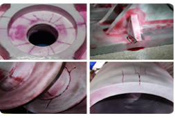
2) LIQUID (DYE) PENETRANT EXAMINATION (DPT):
PRINCIPLE: Capillary Action
SCOPE: To detect surface cracks or defects on various components, except porous components.
 EQUIPMENT USED:
1) Color contrast penetrants
(Fluorescent and Non Fluorescent)
2) Wet Developers
3) Cleaners
METHOD OF TESTING:
After ascertaining the surface condition, a highly sensitive Penetrant is sprayed on the surface. Excess Penetrant is removed after a suitable “Dwell time”. A wet developer is then sprayed on the surface uniformly. Examination for defect indications is done after 7-10 minutes.
DP Test can be conducted on all non-porous materials like metals, Plastics etc.
SOURCE STANDARD: ASTM-E – 165
ACCEPTANCE STANDARDS: As per ASTM/ ASME.
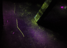
3) MAGNETIC PARTICLE EXAMINATION (MPT):
PRINCIPLE: Magnetic Flux Leakage
SCOPE: To detect surface and subsurface cracks or defects for Ferrous components.
 EQUIPMENT USED:
1) 1500 Amps, AC/HWDC Flaw Detector
2) AC/DC Electromagnetic Yoke
3) Ultraviolet Lamp
SOURCE STANDARD: ASTM-E-709
ACCEPTANCE STANDARDS: As per ASTM/ ASME
METHOD OF TESTING: Dry/ Wet Fluorescent continuous method on Ferrous
Magnetization is done using appropriate coiling techniques and/or by Electromagnetic Yoke. Adequacy for field strength is verified using octagonal field indicator. Water or Kerosene/ solvent based fluorescent Magnetic particles ae sprayed on the areas magnetizes while the field is on. The surface thus sprayed is examined under visible or ultraviolet light for the presence of defects.
Magnetic particle testing can be done on all ferromagnetic materials and machine components like Shafts, Rotors, Casings, Blading, Diaphragms, Valves, Spindles, etc.
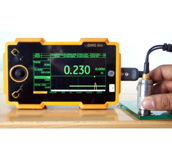
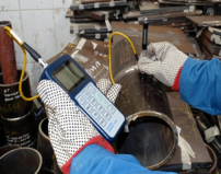
4) ULTRASONIC THICKNESS GAUGING (UTG):
SCOPE: Thickness measurement and Corrosion Monitoring.
 EQUIPMENT USED:
1) Microprocessor Based Ultrasonic Thickness Gauge-GE-KRAUTKRAMER make
2) Twin crystal Probes-various types and Frequencies.
METHOD OF TESTING:
Pulse Echo Contact Method. The usage of an Ultrasonic Thickness Gauge in non- destructive testing, to check material thickness, coating thickness or in combination and for Corrosion monitoring. SOURCE STANDARDS: AS PER ASTM-E-797.
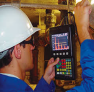
5) ULTRASONIC TESTING (UT):
PRINCIPLE: Acoustic Impedance
SCOPE: For detection of subsurface and internal defects
 EQUIPMENT USED:
1) Microprocessor Based Ultrasonic Flaw Detector GE-KRAUTKRAMER-USM-36
2) Normal, Twin crystal and Angle probes
METHOD OF TESTING:
Pulse Echo Contact Method
A single channel flaw detector is used along with a variety of transducers to suit the particular test systems. They include normal, Shear wave, twin crystal probes of sizes ranging from 5mm and upwards and Frequencies of 1 to 10 MHz The angle probes range from 45, 60, 70 Deg.
Calibrations are done using IIW, V1 and V2 Blocks.
Ultrasonic scanning is done on all accessible surfaces of components like Shafts, Sleeves, White metal line Bearings, Critical Fasteners, New or repaired Weld joints, and etc.
SOURCE STANDARDS: AS PER INTERNATIONAL STANDARDS – ASTM, ASME, etc.
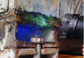
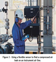
6) ULTRASOUND LEAK DETECTION SURVEY:
SCOPE: To detect leaks in Air, Vacuum and Steam pipelines for improved Productivity.
 EQUIPMENT USED: SDT and Holroyd Makes
METHOD OF TESTING:
Ultrasonic Leak detection can be carried out by aiming the receiver moving it to sides or up/down to locate the strongest (most intense) Ultrasound signals and following the Ultrasound to its source of Leak. The results of each point are compared with respect to the recorded db level and the severity will be categorised. By calculating the CFM value for each leakage location, the cost benefit analysis can be done.
The results are rapid, reliable and traceable and can be implemented in any number of applications in process plants.
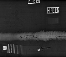
7) RADIOGRAPHY TESTING:
SCOPE: To detect Surface and Subsurface Defects
 EQUIPMENT USED:
1) Camera with Source like Ir-192, Cobalt-60, etc.
2) X-Ray Films
METHOD OF TESTING:
Radiographic Testing (RT), or industrial radiography, is a non-destructive testing(NDT) method of inspecting for hidden flaws/defects and to check the Homogeneity of Materials by using the ability of short wave length electromagnetic radiation (high energy Photons) to penetrate various materials.
SOURCE STANDARDS: AS PER ASTME-94-04, ASME Sec VIII Div-1 etc.
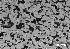
8) METALLOGRAPHY TEST:
SCOPE: To study the present microstructure condition
 EQUIPMENT USED:
1) Micro grinding machine
2) Variable speed polishing machine
3) Field Microscope
4) Replicating consumables
METHOD OF TESTING:
IN-SITU Metallographic examination by surface replication technique.
In this technique, the spot chosen for examination is prepared to get scratch free surface. The spot is then etched with suitable etchant based on material, washed thoroughly and dried. The spot is then examined under portable field microscope and the reverse image of the grain structure is taken on to plastic replicating tape for detailed laboratory examination at higher magnification.
Replication technique reproduces with sufficient accuracy the Metallographic features such as Carbide precipitate distribution. Their morphology and micro voids associated with early stage of creep damage.
9) HARDNESS SURVEY:
SCOPE: To get the qualitative assessment of the material structural changes with digital display
 EQUIPMENT USED: Dynamic hardness tester with digital display
METHOD OF TESTING:
Hardness testing gives qualitative assessment of material & structural changes and is done using a latest Dynamic Hardness tester with digital display based on rebound principle.
Hardness is checked on all important components like Shafts, Rotor, Valve bodies, Spindle, etc, at different locations to check the healthiness of the components. The measured Dynamic values can be converted into various like Brinnell, Vickers and Rockwell etc.
SOURCE STANDARDS: As per International Standards.
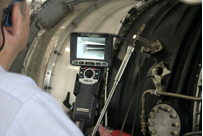
10) BOROSCOPE INSPECTION:
SCOPE: For recognizing defects or imperfections in Inaccessible areas.
 EQUIPMENT USED: XL VU (GE MAKE)
METHOD OF TESTING:
Boroscope is designed to provide the highest performance optical imaging system. A computer-optimized optical train of precision- fabricated lensed capture a high resolution image at the viewing tip and carry it back to the eyepiece, while a fibre-optic bundle carried light in the other direction to illuminate the imaged area. Where it is viewed through an eyepiece or captured by a camera that can then display the image on a monitor. All the images and Video can be saved onto data storage cards and can be used for review.
SOURCE STANDARDS: As per International Standards.