Thermography
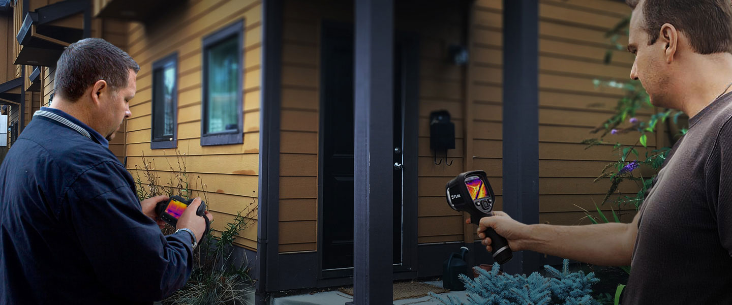
Infrared thermography as a predictive maintenance (PdM) inspection technique is a widely-recognized and effective non-destructive (NDT) testing tool used often to check electrical and mechanical systems, buildings, roofs and facilities. IR is also used to improve manufacturing processes and is utilized in R&D applications.
Our infra-red thermographers are trained and certified by Infrared Institute in ASML Level-I, Level-II and Level-III areas. Our experts with deep experience in carry the thermal survey and submit action reports for implementing corrections.
Why Infrared Thermography?The benefits of using Infrared Thermography include but are not limited to:
- Safety
- Decrease unplanned downtime
- Increased product quality
- Increased equipment reliability
- Increased customer satisfaction through on time, quality product delivery
- Schedule/plan the correct work for outages/relines/rebuilds
Infrared Thermography makes possible the ability to convert an invisible, to the human eye, thermal image into a visual presentation permitting the interpretation of the thermal patterns into useful diagnostic information. An electrical panel to the human eye appears as in Fig 1.
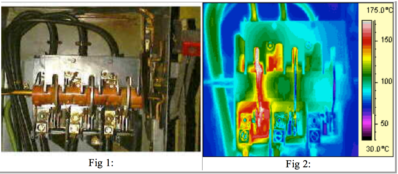
What we don't see in Fig.1 is the increased resistance caused by dirt build-up, looseness or improper installation. The thermal image in Fig. 2 quickly and safely permits the inspection and identification of faults and affords us the opportunity to evaluate the current on line condition. Additionally it allows for the determination of the correct action; repair or replace, and when to complete the action; immediately or on a scheduled outage.
While Infrared has the following advantages:- Remote measurement
- Rapid inspection
- Thermal patterns undisturbed
- Guess work taken out of the equation
- Equipment remains on-line
- Direct line of site required
- Hot objects in background affect results
- Equipment is expensive
- Electrical
- Refractory
- Process Piping
- Mechanical
- Product Monitoring
- Process Assessment
- Research and Development
Electrical components surveyed on a scheduled frequency include electrical panels, motor control circuit relays, transformers, breakers and fuses. All are inspected with a minimum frequency of 12 months and a maximum frequency of 3 months. Frequency of inspection is determined by voltage, operating conditions (loading requirements), cycling, environment and whether they are part of a constraint operation. During inspection it is determined whether remedial action is required immediately or may be scheduled in the future. All data is captured and reported to the responsible user for their records. Also included are recommendations for remedial action. After remedial action is completed the affected components are rescanned to insure success of the repairs. It should be noted that we are not always inspecting for hot components but may also detect non-operating conditions such as the example below.
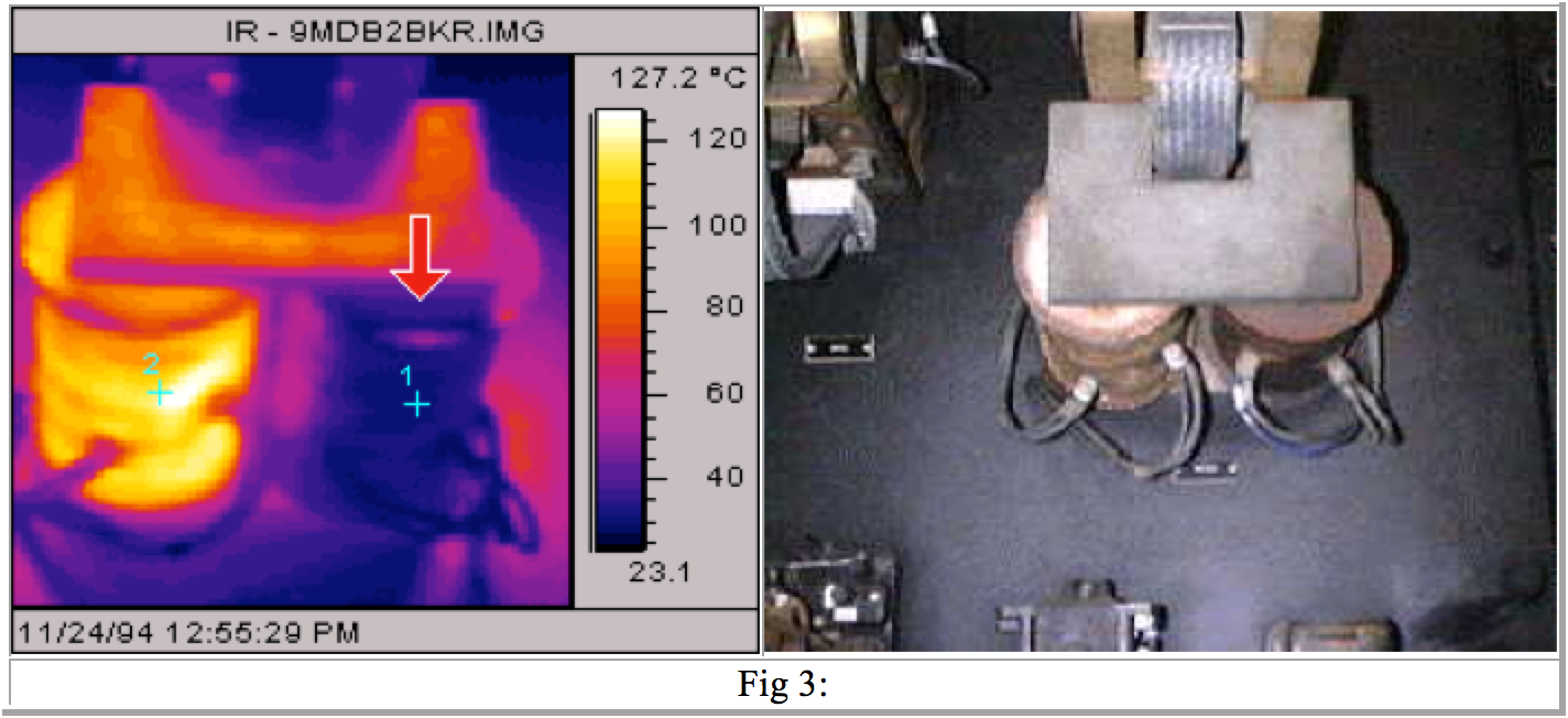
In Figure 3 above, it can be seen that we are not always looking for a "hot spot" or thermal anomaly. In this instance the Open Coil Anneal crane operator reported that while the crane was still operable the controls and responses to the control movements were very sluggish or slow. Upon investigation it was discovered that the open coil on the crane contactor was the cause of the sluggish response. The open windings did not generate any heat as there was no current flow. In addition to the poor response to the operator's controls, it can be seen that the coil on the left would eventually fail due to over current loading.
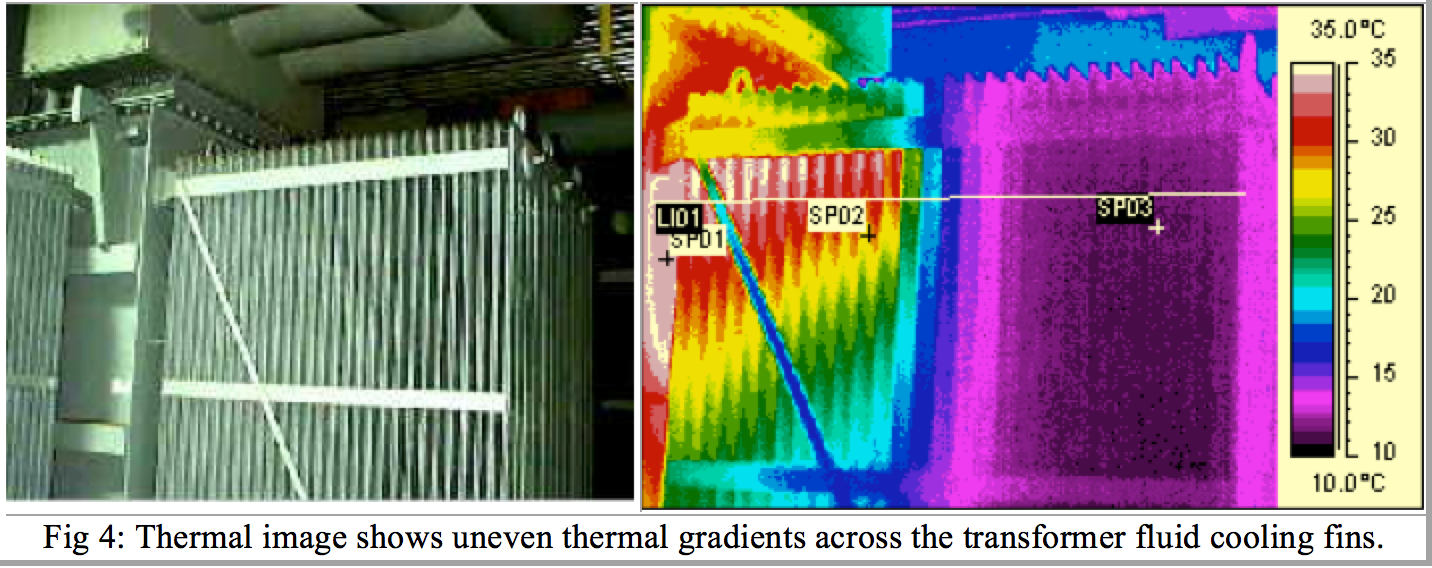
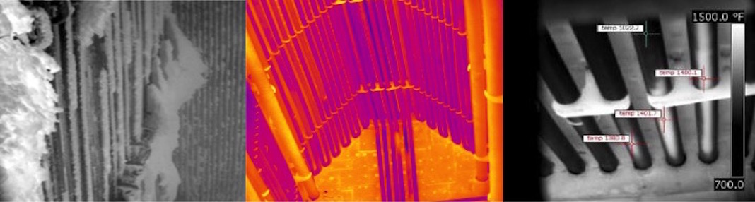
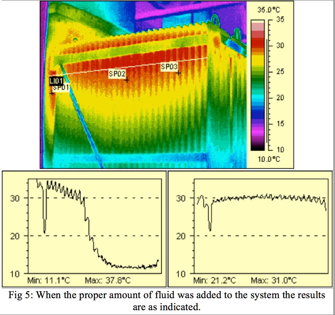
High voltage transformers are inspected as part of an assets routine inspection. If a standard 13,8000 volt transformer operates above 80°C for an extended period of time the transformer life will be greatly reduced. Fig. 4 is the result of the inspection of a 13,800 volt transformer. It can be seen that the cooling pattern of the transformer oil is not occurring as per the design. Investigation into the cause of the uneven oil cooling within the heat exchanger cooling fins discovered that the oil level was in fact insufficient to fill the cooling fin header. This led to poor distribution of fluid throughout the cooling unit, insufficient cooling and a thermal pattern as in Fig 5.
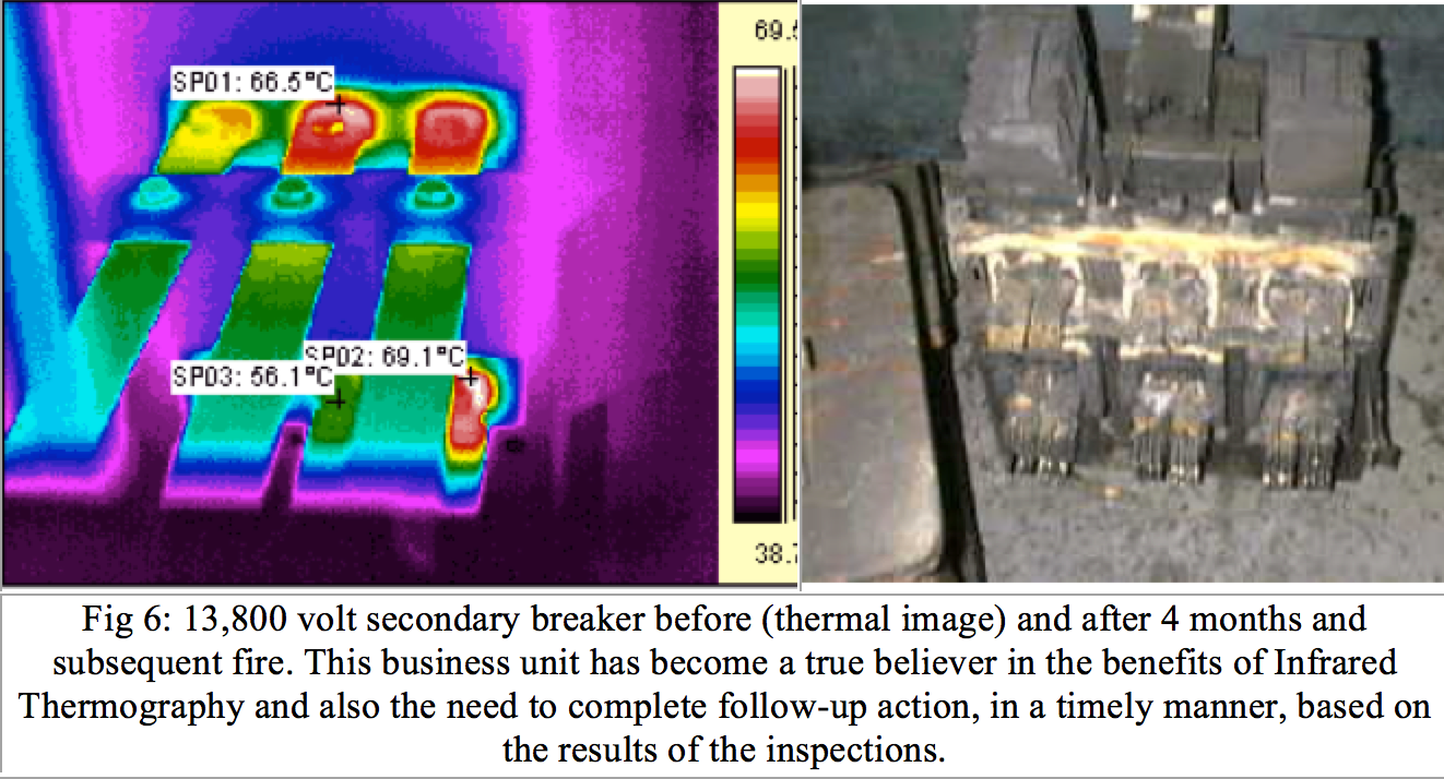
While the Condition Based Monitoring portion of our Equipment Maintenance Program has been ongoing for many years, there are times when reaction to the detected anomaly is not adequate or may be postponed for too great a period of time as to allow for the effective repair to take place. The result is usually typical of Fig 6. In this instance a "13,800 V/600 V" secondary breaker bus stabs were detected as being faulty. This information along with all thermograms was forwarded to the business unit. The client did not plan a shutdown to correct the situation with the end result being an unplanned outage of the related equipment and production. Fortunately there was no long term effects, collateral damage or injuries.
Refractory Applications
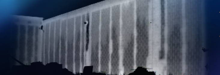
Refractory is a key component within many of the processes involved in the making of steel. It is a necessity to monitor the condition as it naturally deteriorates or becomes damaged in the process. Most refractory applications are impossible to see during normal operation and the process must be shutdown in order to determine the extent and type of repair necessary. Infrared Thermography allows for the inspection to take place with the process on-line and no loss of production. The repairs can be anticipated and scheduled. If necessary equipment can be taken out of service immediately.
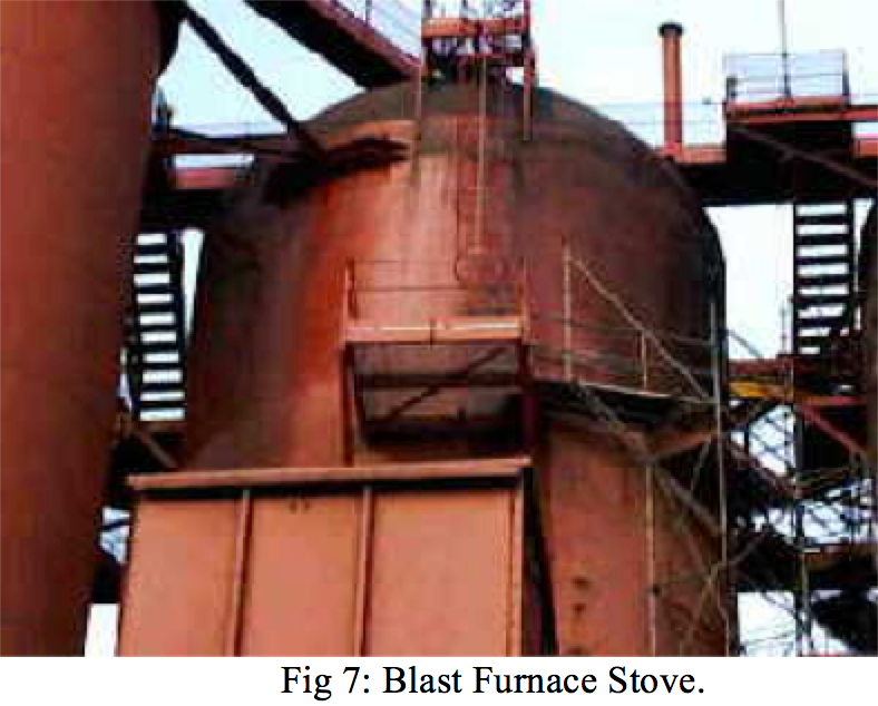
The Blast Furnace stoves are essential in providing hot, dry air to the process for the making of the quality iron necessary to the KOBM steelmaking process. Stoves can cost as much as $22 million dollars (CDN) to reline. Infrared Thermography is employed to monitor the condition of the refractory and to monitor repairs. The stoves can be repaired without having to be shutdown and entered. Grout material is pumped through nozzles to the areas identified on the thermal image.
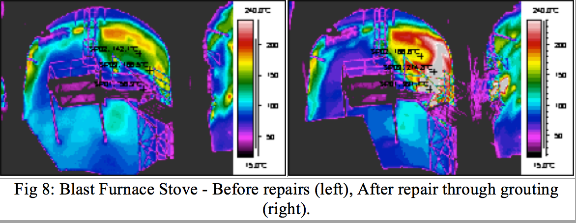
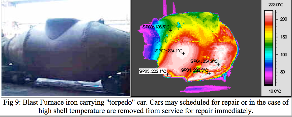
Infrared thermography monitoring of the refractory in the stoves has contributed significantly in the life extension of the stoves between relines. Stoves now have an average of 5 years longer life between relines. An added benefit is the ability to monitor the repairs for their effectiveness. This same monitoring is used to determine the refractory condition in the 22 "torpedo" cars which carry the molten iron first to the desulphizing station and then on to the KOBM steelmaking process. Along with the normal benefits to cost and equipment reliability, this also extends the life of the cars significantly. In the past the cars were taken out of service and relined often times too early due to the risks associated with transporting molten iron throughout the plant. Cars are now monitored and taken out of service when required for refractory repairs. The materials and repairs can be assessed for their effectiveness in providing the required insulating values. These results can be used to modify procedures and materials to produce the most desirable results.
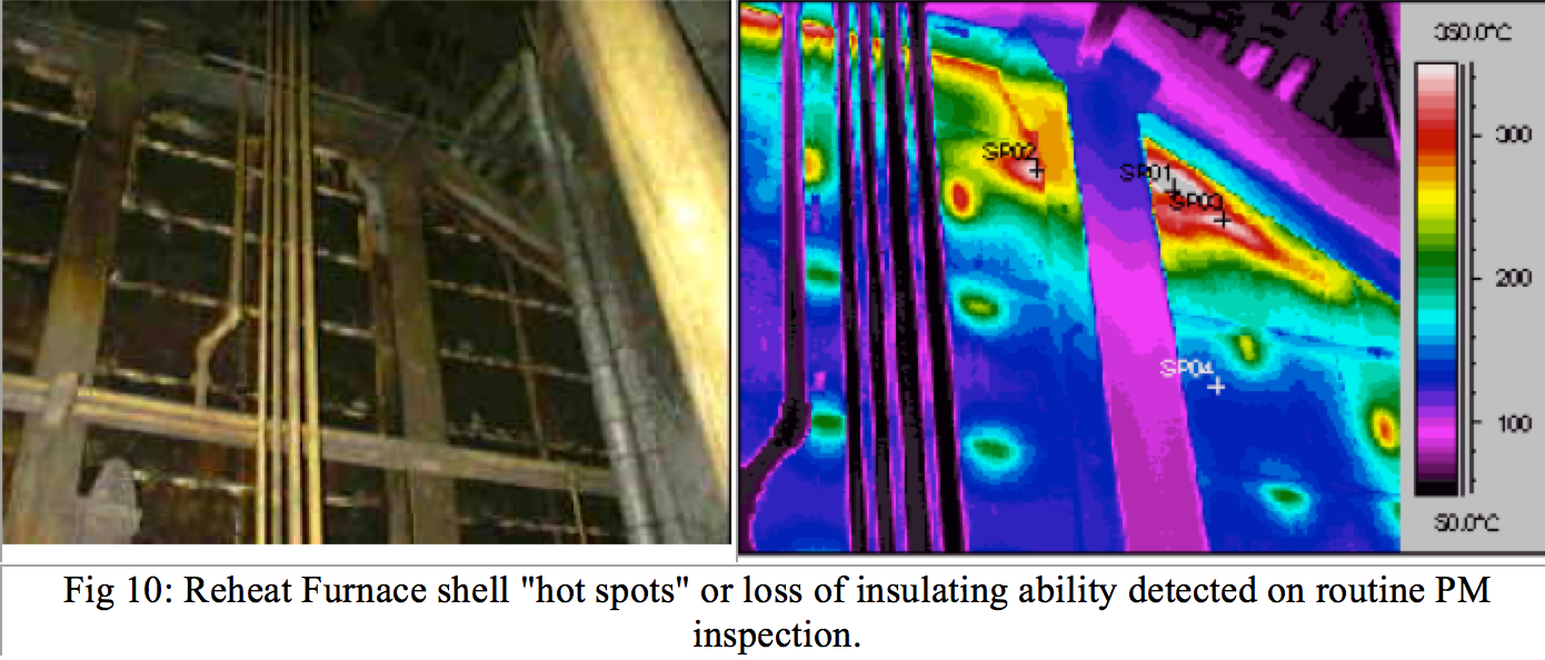
Fuel savings are an additional benefit to the monitoring of the refractory condition in the slab reheat furnaces at the Hot Mill. Slabs are reheated for uniformity throughout the slab and ensure the correct temperature for rolling. These furnaces consume large amounts of fuel so the refractory condition is extremely important. The monitoring is on a quarterly frequency and the reports are used to determine efficiency and repair requirements. All repairs are monitored after return to production status.
Process Piping:
An important link from process to process or within a process, are the piping systems which carry fuels, by-products or any requirement for the process. Process piping may be referred to as "the arteries" of the production sequence. Without the efficient transportation of the various gasses or fluids many processes will suffer from quality, throughput issues, or may even be shutdown. One of the more commonly associated functions is the removal of heat from the process or media. While this function is commonly acknowledged, one of the functions not normally associated with process piping is the transfer of gasses or fluids while maintaining the temperature or a predetermined cooling rate. Infrared Thermogarphy is used to determine restrictions in flow, leakage at connections, leakage throughout the system due to corrosion/erosion/age.
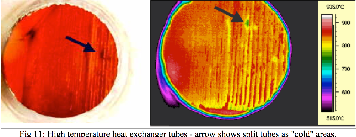
Fig. 11 shows a heat exchanger with cracked tubes. Efficiency of the heat exchanger has obviously been compromised. The cracked and leaking tubes were found on a pre-shutdown inspection. This allows for the planning and scheduling of tube repairs/replacement to be included in the scope of overall repairs. All repairs are monitored after start-up to insure quality of repairs and the resulting return to an efficient operation.
Process piping carrying fluids is often susceptible to fouling or build-up causing reduced flow due to a reduced cross-sectional area. Many liquid transportation lines must transport fluid that is heavily contaminated with particulate. The particulate will drop out of solution due to temperature reduction, vertical pipe rises or reduced cross-sectional areas as found at valves, orifice plates, etc.
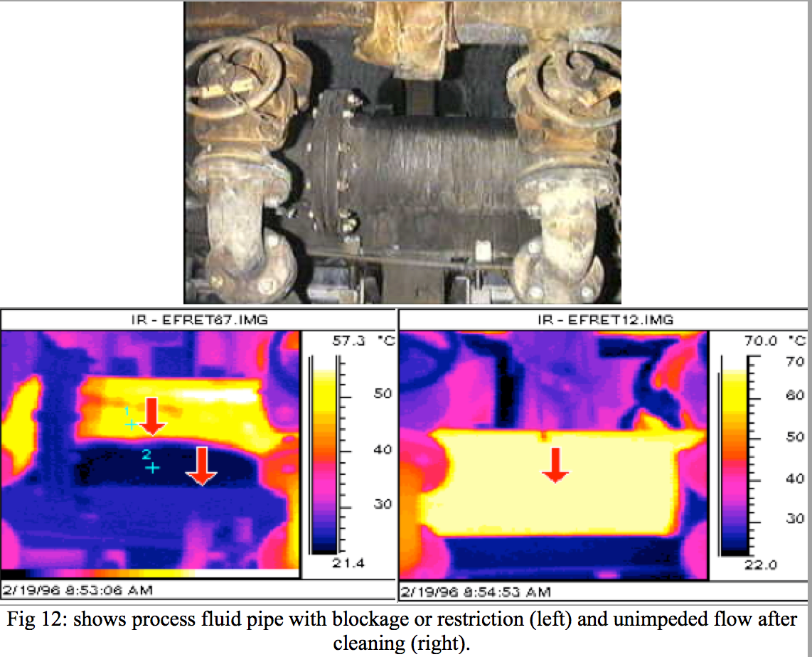
Many of the gases that are transported by process piping are often at elevated temperature. During the transportation the gasses lose temperature and consequently the particulate held in the flow may drop out. If the piping changes elevation or direction the reduction with a resultant change in velocity or flow patterns, this is the area where build-up or sediment will occur. Although changes in the thermal patterns on uninsulated lines can be detected year round some of the insulated lines can only be inspected when ambient temperatures are lower than the process gasses. This requires the correct scheduling timeframes in order to provide the necessary accuracy in the results.
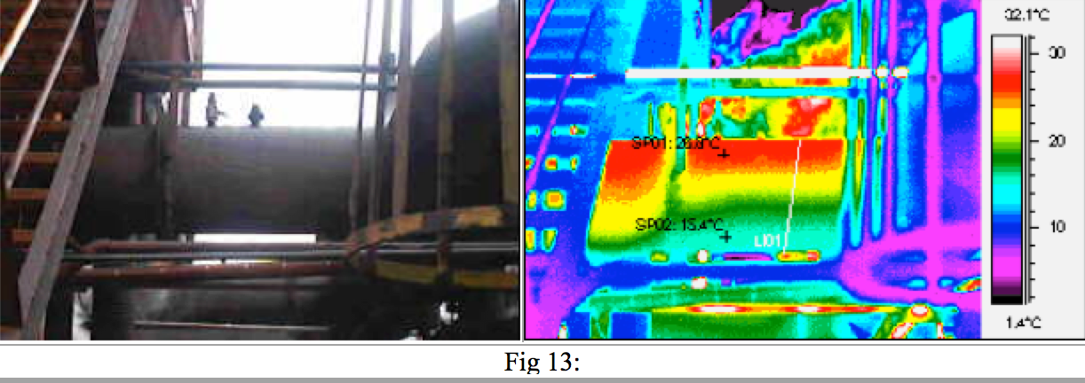
Fig. 13 - Coke oven gas line with naphthalene build-up. Napthalene is a tar like substance which separates out with a reduction in temperature as the gas is transported from the coke ovens where it is a by-product to the next process where it is used as a fuel. By conducting the Infrared inspection, build-up is detected and measures taken before gas flow is restricted sufficiently to cause the use of higher priced fuels or process shutdown. In many cases the addition of chemicals or steam can "liquify" the build-up and move it to an accessible drip leg where it can be removed.
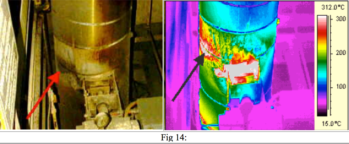
Mechanical failure can also be detected. Fig. 14 shows a hot air duct at the remote soaking pits. The gasket at the valve has failed and was detected during the quarterly scan of the remote reheat furnaces. The piping is insulated with the insulation being covered with a highly reflective covering. Normally this leak of the hot air due to a failed gasket would have been difficult to detect. In this case the leak would have gone undetected resulting in an increase in fuel consumption for a significant time. The leakage caused by the defective gasket in this case was excessive and even though the insulation covering was highly reflective the thermal pattern was easily recognized. It is important to note that this condition was allowed to continue for several months. This was necessitated as the reheat furnace had to be shutdown and allowed to cool before repairs could be affected. The repair was monitored during start-up after reline.
Combining Predictive Technologies:
Infrared Thermography is only one of the many predictive technologies that may be used to determine the root cause of equipment failures. Any one of the technologies may be successful at any one time but in some cases more than one technology is required to solve the problem. The following examples highlight this.
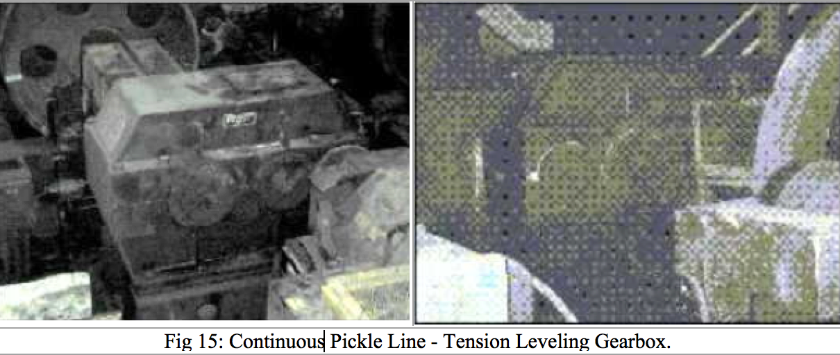
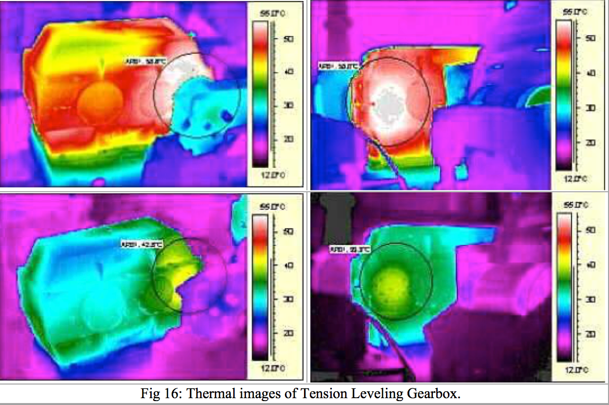
Fig.15 and Fig 16 - Tension leveling gearbox- During normal inspection the gearbox was determined to be operating at elevated temperatures (Top Thermograms). There was little or no indication that a specific failure mechanism was in place i.e. bearing failure, coupling misalignment, etc. It was recommended that a lube sample be taken.
The lube analysis indicated particulate present, unserviceable fluid and general degradation. The gear oil was drained and flushed from the box and new gear oil added. This change resulted in operation returning to normal. The fluid was monitored for several weeks and remained in a serviceable condition. See Fig. 16 bottom thermograms
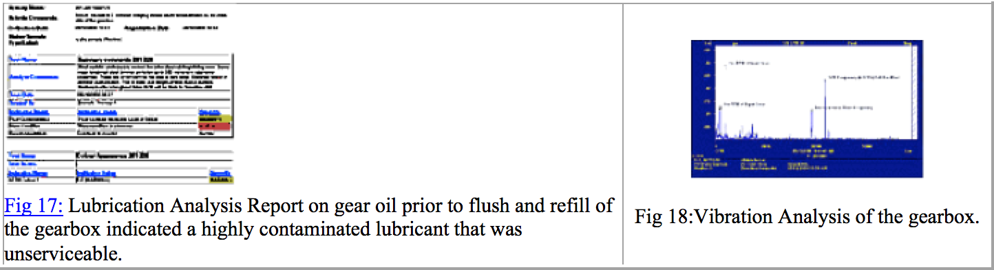
Fig. 18 The lubrication analysis also pointed to some advanced wear within the gearbox. A vibration study indicated some misalignment within the intermediate and secondary drives. This was corrected on the next shutdown.
The above example illustrates how the predictive technologies of Vibration Analysis, Lubrication Analysis and Infrared Thermography were used together to prevent the catastrophic failure of the tension leveler.
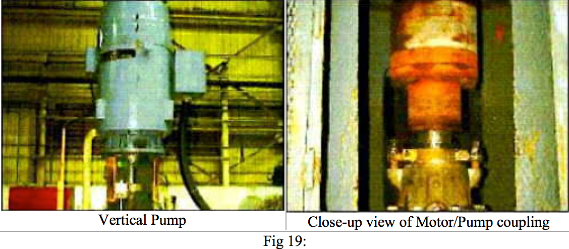
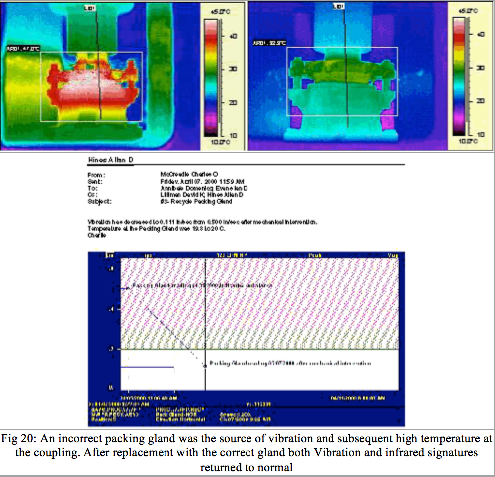
Fig 19 - these are photos of a large vertical pump and a close-up of the motor shaft and pump shaft coupling. After a rebuild necessitated due to impeller failure (debris in suction inlet) routine start-up vibration inspection found this pump to have higher than normal axial readings. High axial readings indicated misalignment of the motor/pump shaft coupling. The coupling alignment was checked and found to be acceptable. Subsequent vibration readings continued to indicate misalignment. Infrared Thermograhy was used to try and determine the source of the vibration. The thermograms indicated the source of the vibration was at the coupling. After further inspection it was detected that an improper packing gland had been used during the rebuild. The gland was replaced with the results shown below.
In summary, Nondestructive Testing has always been a valuable tool within the maintenance community with its versatility, accuracy and repeatability has become a major player in the battle to eliminate the failures which lead to quality and throughput consequences, collateral damage and personal injuries. With the ongoing advancements in equipment and technology, the use and importance of this technique will also continue to grow. The examples in this paper are only a few of the many instances where Infrared Thermography has proven to be the desired technique.