Oil Wear Particle Analysis / Ferrography
Using Ferrographic technologies, MVS ACMEI provides the world’s most effective wear and debris particle analysis programs. Highly skilled laboratory technicians extract, classify, and visually analyze wear particles and solid contaminants.
What does Ferrography mean?Ferrography is the study of ferrous metal wear, and comes from the Latin word "ferrum," which translates to "iron."
Ferrography is a technique for analyzing the particles present in fluids that indicate mechanical wear. It has been in use since 1970, and provides microscopic examination and analysis of debris (particles) found in lubricating oils.
Ferrography can be used in laboratory testing for:
- Lubricants and engines
- Evaluating oils
- Predicting lubricant failure
- Studying lubricant wear debris.
Ferrography is a technique that is used to monitor for wear modes that are undetectable to spectroscopy. It is used to predict and diagnose equipment problems. It is a series of laboratory tests used to determine the condition of used lubricants and equipment components, over a period of time.
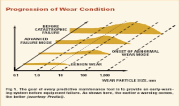
By monitoring particles generated by wear or environmental contamination, Ferrography experts are able to detect critical stages of accelerated wear that precede costly and dangerous component failures. A Ferrographic analysis determines the number, size and shape of wear particles.
Two Ferrographic techniques have been developed to monitor the levels of wear particles in lubricated systems:
- Direct-reading ferrography - Gives a direct measure of the amount of ferrous wear metals present in a sample of oil
- Analytical ferrography - Allows an analyst to visually examine wear particles present in an oil sample
Ferrography has advanced as one of the premier predictive maintenance and analytical tools. This technique for wear particle analysis has become prominent in the paper industry, industrial plants with automated operations and in health care with artificial joints and limbs. In the hands of a skilled analyst, ferrography is capable of detecting active machine wear and can often provide a "root cause" based on the morphology of the wear particles.
What does Wear mean?
Wear is a process of interaction between surfaces, which causes the deformation and removal of material on the surfaces due to the effect of mechanical action between the sliding faces. Wear also refers to the dimension loss of plastic deformation. Plastic deformation leads to wear; it causes the deterioration of metal surfaces, which is known as "metallic wear".
Wear is the result of many things such corrosion, erosion, abrasion, chemical processes, or combinations of these factors. The processes of wear are studied in the field of tribology.
Wear
Wear is a phenomenon through which the deformation of surfaces of materials occurs. Common types of wear include:
1. Adhesive Wear: Unwanted displacement and debris production resulting in the creation of frictional contact between surfaces. It is visible by fretting, pits, holes, or scales transfer.
2. Abrasive Wear: Loss of material resulting from sliding hard surfaces. Can be seen as scratches, grooves, or corrugations.
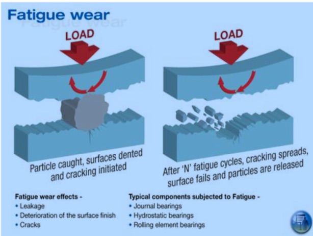
3. Surface Fatigue: Material surface weakened by cyclic loading. Can be witnessed as tears or small holes.
4. Fretting Wear: A little shift of the contacting surfaces under load in oscillatory motion.
5. Erosive Wear: Results from impact of sharp particles on a surface. First seen as changes in surface finish.
In abrasive wear, hard particles, contaminating oil, insufficient metal hardness, and hard metal with rough surface against soft metal promote wear. In erosive wear, the high velocity of sharp particles increases wears. On the other hand, in surface fatigue, cyclic stress over long periods, water, dirt in oil and particles of metal with sharp edges enhances wear. In a corrosive environment, corrodible metals, rust-promoting conditions, and high temperatures facilitate wear.
Specific coatings are used to prevent the effects of wear as well as to repair wear surfaces. This saves costly components from replacement and failure. In order to select the appropriate coating, the wear type should be identified.
What does Abrasive Wear mean?
Wear, in material science, simply means erosion or the displacement of a material from its original form. It can happen on its own or be caused by contact with another surface. Abrasive wear takes place when a rough, hard surface glides across a surface that is relatively softer.
Abrasive Wear
Abrasive wear is typically categorized by the contact environment and the type of contact. The contact type defines the abrasive wear mode. In general, there are two types of abrasive wear:
- Two-body abrasive wear - This type takes place when hard particles or grit eliminate material from the opposing surface.
- This can be best described by thinking of a material being displaced or removed through a plowing or cutting operation.
- Three-body wear - This occurs when the particles are unconstrained and are able to slide down and roll on a surface. The environment of contact defines whether the classification of wear is a closed or open type. An open wear environment takes place when surfaces are adequately displaced to become free of each other.
- Fragmentation - This takes place when a certain material is separated from a façade through a cutting process. This results in indenting abrasive that can cause localized fracture within the wear material. Cracks spread freely throughout the wear, leading to further material removal.
- Cutting - This occurs when a material separates from a surface in tiny chips or debris, with only minimal or no displacement to both of the groove sides. This is similar to conventional machining.
- Plowing - This occurs when there is material displacement sideways, moving away from the particles of wear. This results in groove formation that does not involve removal of material. The displaced material creates ridges along the grooves that may be eliminated by consequent abrasive material passage.
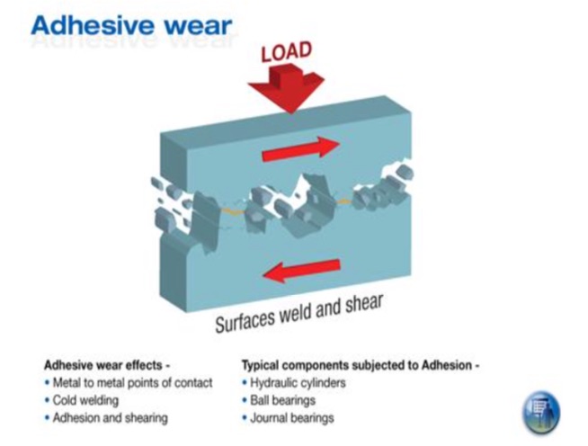
Adhesive wear is a phenomenon which occurs when two metals rub together with sufficient force to cause the removal of material from the less wear-resistant surface. This wear is dependent on physical and chemical factors such as material properties, presence of corrosive atmosphere or chemicals, as well as the dynamics such as the velocity and applied load.
This phenomenon is considered corrosion by means of mechanical action rather than chemical reaction. ASTM G77 provides specifications and testing procedures for adhesive wear testing. Adhesive wear is also known as sliding wear or scuffing wear.
Adhesive Wear
When two metal surfaces come into contact with each other, they initially touch only at a few rough points. Friction and wear originate at these points. When a compressive load is applied, these rough points are plastically deformed and finally welded together because of the high pressure that is created. As sliding continues, these bonds are broken, producing cavities on one surface and depressions on the second surface. Abrasive particles detach and rub against the surface, contributing to wear.
There are several types of adhesive wear:
- Sliding wear - when one solid slides over another other solid
- Galling wear - intense form of adhesive wear
- Scoring/scuffing wear - formation of grooves and scratches in the sliding direction
- Oxidative wear - wear in unlubricated ferrous systems
- Cold welding
- Scoring
- Pits
- Seizing
- Built-up edges
- Scuffing
- Tool breakage
- Selecting softer materials
- Increasing the hardness of the material
- Selecting highly incompatible pairs, such as silver on cobalt
- Selecting materials having low surface energy
- Rubbing Wear
- Severe Sliding Wear
- Cutting Wear
- Rolling Element Fatigue (Rolling Element Bearings and
- Gear Systems)
- Fatigue Spalls
- Spheres
- Laminar Particles
- Red Oxides
- Dark (black) Oxides
- Non Ferrous Metals
- Corrosive Wear
- Inorganic Contamination
- Organic Contamination
- Friction Polymers
- Solid Lubricant Additives
- Heat Treatment of Ferrous Metals
- The specific type and quantities of metallic and nonmetallic debris present
- A color photomicrograph of the ferrogram, providing visual documentation of the metallic concentrations
- An assessment of the sampled machine’s or component’s overall wear status
- Interpretation of the ferrography results detailing the cause(s) and the source(s) of problems detected
- Recommendations for corrective action. The wear mechanisms present in the sample are then analyzed by a trained ferrographer. Types of wear that can be observed follow below.
1) High Alloy Steel: particles are found in chains on the slide and appear gray- white. The distinguishing factor in the identification between high alloy and white nonferrous is position on the slide. If it is white and appears in a chain, it’s deemed to be high alloy. Otherwise, it’s considered white nonferrous
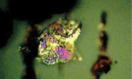
2) Low Alloy Steel: particles are also found in chains and appear gray-white but they change color after heat treatment. After heat treatment they usually appear as blue particles but can also appear pink or red.
3) Cast Iron: particles appear gray before heat treatment and a straw yellow after the heat treatment. They are incorporated in chains amongst the other ferrous particles.
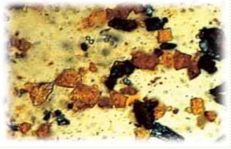
4) Copper particles: usually appear as bright yellow particles but the surface may change after heat treatment. These also will be randomly deposited across the slide surface with larger particles resting at the entry point of the slide and gradually getting smaller towards the exit point of the slide.
5) Red Oxides (Rust): polarized light readily identifies red oxides. Sometimes they can be found in chains with the other ferrous particles and sometimes they are randomly deposited on the slide surface. A large amount of small red oxides on the exit end of the slide is generally considered to be a sign of corrosive wear. It usually appears to the analyst as a "beach" of red sand.
6) Babbitt particles: consisting of tin and lead appear gray, sometimes with speckling before the heat treatment. After heat treatment of the slide, these particles still appear mostly gray, but with spots of blue and red.
7) Dark Metallic Oxides: deposit in chains and appear dark gray to black. The degree of darkness is indicative of the amount of oxidation.
8) Fibers: Fibers typically from filters or outside contamination, are long strings that allow the transmitted light to shine through. They can appear anywhere on the ferrogram, however they tend to be washed towards the exit end.
9) Contaminants: are usually dirt (silica) and appear as white crystals and are identified since they are somewhat transparent.
10) White nonferrous particles: often aluminum or chromium, appear as bright white particles. They are deposited randomly across the slide surface with larger particles getting collected against the chains of ferrous particles. The chains of ferrous particles typically act as a filter that collects contaminant
MVS ACMEI Oil Analysis Service
| OIL PHYSICAL PROPERTIES | Test Method | Minimum Sample (ml) |
|---|---|---|
| Total Acid Number (TAN) | ASTM D664 | 30ml |
| Total Base Number (TBN) | ASTM D4739 | 5 ml |
| Kinematic Viscosity | ASTM D7279 | 1 ml |
| Water by Karl Fischer, ppm | ASTM D6304 | 3 ml |
| Pour point °C | ASTM D97 | 100 ml |
| Fire point °c(°F) | ASTM D92 | 100 ml |
| Flash point °c(°F) | ASTM D3828 | 100 ml |
| Sp Gr-g/ml | ASTM D1298 | 100 ml |
| Density-lb/gal | ASTM D1298 | 100 ml |
| Copper Strip Corrosion, 3hrs @ 100°c | ASTM D130 | 100 ml |
| Foaming-Seq, 1, 2, 3 | ASTM D892 | 50 ml |
| IR % Soot Content | ASTM D7686 | 1 ml |
| Particle Count | ISO 4406 / NAS | 50 ml |
| Elements in Oil, RDE-ICP | ASTM D6595 | 3 ml |
| Spectroscopy FTIR | ASTM E2412 | 3 ml |
| Membrane Patch Colorimetry (MPC) | ASTM D7843 | 50 ml |
| Rotating Pressure Vessel Oxidation Test (RPVOT) | ASTM D2272 | 500 ml |
| Ferrography, Analytical | ASTM D7690 (modified) |
3 ml |
| Ferrography, Direct Reading | in-house | 3 ml |
Wear Metals / Elemental Analysis
| Wear Element | Contaminants | Additives |
|---|---|---|
| Iron (Fe) | Silicon (Si) | Molybdenum (Mo) |
| Chromium (Cr) | Sodium (Na) | Magnesium (Mg) |
| Aluminium (Al) | Potassium | Calcium (Ca) |
| Copper (Cu) | Boron (B) | Barium (Ba) |
| Lead (Pb) | Phosphorous (p) | |
| Tin | Zinc (Za) | |
| Silver (Ag) | Cadmium | |
| Nickel (Ni) | Vanadium |